Ship Hull Design, Types, and Structure: A Technical Guide
What is a ship hull?
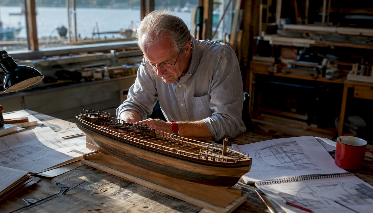
A ship hull is the complete watertight structural body of a vessel, encompassing the sides, bottom, and any covered deck. It is not simply the bottom of the boat. The hull includes every structural element from the keel at the lowest point to the deck edge, and the line where it meets the water surface is called the waterline.
The hull performs three core functions simultaneously:
- Buoyancy provision: displaces water to generate the upward force that keeps the vessel afloat
- Structural support: distributes loads from cargo, equipment, waves, and the vessel’s own weight
- Protection: forms a watertight barrier shielding internal machinery, cargo, and crew from water ingress
A common misconception is that the hull refers only to the underwater portion. The superstructure, masts, and funnels sit above the hull, but the hull itself extends from keel to weather deck. Naval architects and the U.S. Coast Guard treat the entire watertight body as the hull for inspection and certification purposes.
Types of ship hulls and how shape drives performance
Hull shape determines how a vessel moves through water, how fast it can travel, and how much fuel it burns. Three primary categories define most commercial and recreational vessels.
Displacement hulls push through the water rather than rising above it. The vessel’s weight is supported entirely by buoyancy at all speeds. This design suits cargo ships, tankers, and long-range cruising sailboats where fuel efficiency and load capacity outweigh the need for speed. Speed is limited by waterline length; longer hulls allow higher maximum hull speeds.
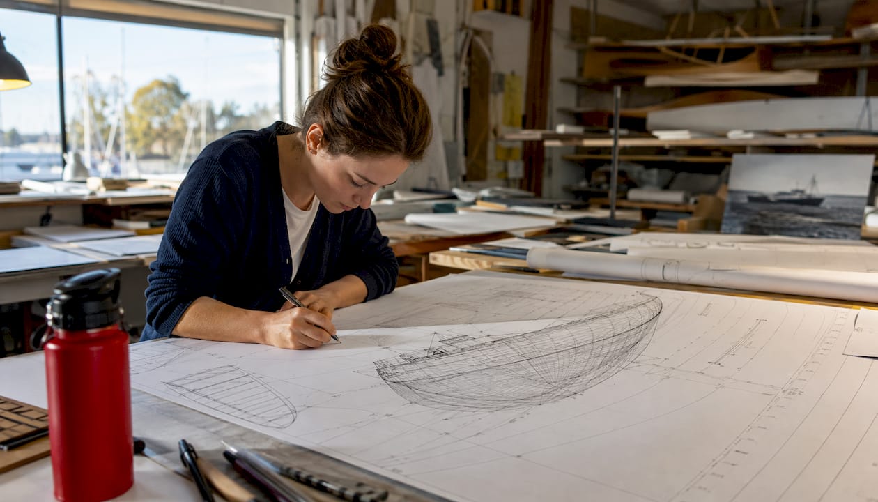
Planing hulls are configured to generate dynamic lift as speed increases, causing the bow to rise and the hull to skim across the surface. Draft decreases at speed, reducing wetted surface area and drag. Powerboats, personal watercraft, and high-speed patrol vessels use planing hulls. They require more engine power to reach planing speed but deliver fast, efficient performance once on plane.
Semi-displacement hulls (also called semi-planing) generate moderate dynamic lift while still relying primarily on buoyancy. They offer a practical compromise between the fuel economy of displacement designs and the speed potential of planing forms. Many offshore patrol vessels and larger sport cruisers use this configuration.
Hull cross-section geometry adds another layer of classification:
- Flat-bottom hulls: high initial stability, high drag, best in sheltered inshore waters
- V-bottom (deadrise) hulls: deadrise angles of 6°–23°; deeper V shapes (18°–23°) handle rough water better but need more power to plane
- Hard-chine hulls: sharp angular transitions between bottom and sides; resist rolling in calm water, more efficient to build
- Round-bilge hulls: smooth curved transitions; the most widely used form in modern vessels; more seakindly in waves
- Multi-chine hulls: approximate a curved form with several angular panels; less drag than flat-bottom, more complex to build
Pro Tip: When selecting a hull type for a specific application, prioritize sea conditions over top speed. A deep-V planing hull that performs brilliantly in flat water can pound heavily in a chop, while a round-bilge displacement hull handles offshore swells with far less stress on crew and structure.
Hull form design and key naval architecture metrics
Hull form design is the discipline of shaping a vessel’s underwater body to meet specific performance, stability, and efficiency targets. Engineers use a set of dimensionless coefficients to characterize and compare hull forms objectively.
Block coefficient (Cb) is the most widely cited metric. It expresses how fully the hull fills the rectangular box defined by its length, beam, and draft:
Cb = Displacement Volume ÷ (Length × Beam × Draft)
Full-form vessels such as bulk carriers and tankers have high block coefficients indicating fuller hull shapes. Finer, faster vessels like container ships and naval combatants have lower block coefficients reflecting more slender forms. A higher block coefficient means more cargo capacity but greater wave-making resistance at speed.
| Vessel Type | Typical Block Coefficient |
|---|---|
| Bulk carrier / tanker | High |
| General cargo ship | Moderately high |
| Container ship | Moderate |
| Naval combatant / fast ferry | Low |
Three additional coefficients round out the standard toolkit:
- Prismatic coefficient (Cp): ratio of displaced volume to the volume of a prism with the same midship cross-section area and length; governs wave-making resistance at speed
- Midship section coefficient (Cm): fullness of the midship cross-section relative to its bounding rectangle; affects stability and resistance
- Waterplane area coefficient (Cwp): fullness of the waterplane relative to its bounding rectangle; influences initial stability and trim behavior
The Froude number (Fn) defines the operating regime. Displacement hulls operate at Fn below roughly 0.4; semi-displacement hulls span 0.4–1.0; planing hulls operate above 1.0. Crossing these thresholds without the right hull form wastes fuel and stresses structure.
Modern hull form design relies on CAD and CFD tools to evaluate thousands of geometric variations before a single plate is cut. CFD simulations predict pressure distribution, wave patterns, and resistance with accuracy that hand calculations cannot match, reducing costly redesigns during construction.
Hull structural elements, materials, and strength
A hull’s structural integrity depends on how its primary members work together to distribute loads across the entire body. The key components are:
- Keel: the backbone running along the centerline at the bottom; resists longitudinal bending and grounding loads
- Frames: transverse ribs spaced along the hull length; maintain cross-sectional shape and transfer loads to the keel and plating
- Stringers: longitudinal members running parallel to the keel; resist bending along the ship’s length
- Plating: the outer skin attached to frames and stringers; provides the watertight envelope and contributes to overall bending strength
- Bulkheads: transverse watertight walls that divide the hull into compartments; critical for damage stability and structural rigidity
- Decks: horizontal structural platforms that close the top of the hull and carry deck loads
Hull construction materials each bring distinct trade-offs:
Steel remains the dominant material for commercial and naval vessels. It offers high tensile strength, weldability, and low cost but requires active corrosion protection through coatings and cathodic systems.
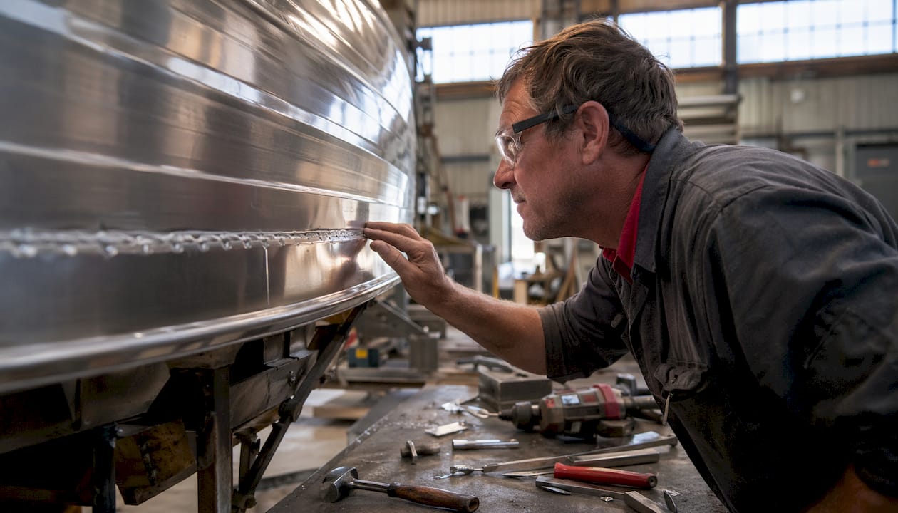
Aluminum is roughly one-third the density of steel, making it the preferred choice for high-speed vessels, patrol boats, and superstructures where weight reduction directly improves performance. Its natural oxide layer provides corrosion resistance, though galvanic corrosion at steel-aluminum interfaces requires careful engineering.
Fiber-reinforced composites (fiberglass, carbon fiber laminates) dominate recreational boat construction and are growing in naval applications. They offer excellent strength-to-weight ratios, corrosion immunity, and design flexibility, though repair after impact damage is more complex than with metal hulls.
Wood persists in traditional boatbuilding and restoration work. Modern epoxy-saturated wood construction (cold-molded or strip-planked) can match composite performance, but maintenance demands are higher.
Pro Tip: Local loads from deck equipment, cranes, and heavy machinery create concentrated stress points that the global hull girder analysis may not fully capture. Always verify that frames and stringers in high-load zones are sized for local bending, not just the overall longitudinal strength calculation.
How buoyancy keeps a hull afloat
Buoyancy is the upward force a fluid exerts on a submerged or partially submerged body, and it is the reason any hull floats. Archimedes’ principle states that this upward force equals the weight of fluid displaced by the hull. When a vessel’s total weight equals the weight of water displaced by its submerged volume, the hull floats at equilibrium.
Hull shape directly controls how much water is displaced at any given draft. A wider, fuller hull displaces more water for the same depth, generating greater buoyancy. A narrow, fine hull displaces less at the same draft, requiring deeper immersion to support the same weight.
Stability depends on the relationship between two key points:
- Center of buoyancy (B): the centroid of the underwater volume; the point where the resultant buoyant force acts upward
- Center of gravity (G): the point where the vessel’s total weight acts downward
When the hull heels, the center of buoyancy shifts toward the low side as the underwater volume changes shape. If this shift generates a righting moment that returns the vessel upright, the hull is stable. If G is too high relative to B, the righting moment becomes negative and the vessel capsizes.
Key factors that influence hull stability:
- Beam (wider hulls have higher initial stability)
- Hull depth and freeboard
- Weight distribution and vertical center of gravity
- Hull form at and above the waterline
Pro Tip: Watertight integrity is not optional. A single flooded compartment shifts the center of gravity upward and reduces the available righting moment. Bulkheads, watertight hatches, and properly sealed through-hull fittings are structural safety features, not conveniences.
Common hull terminology you need to know
Understanding hull geometry requires a working vocabulary. These are the terms naval architects and marine surveyors use consistently:
- Draft (T or d): vertical distance from the bottom of the keel to the waterline; determines how much water depth the vessel needs
- Beam (B): maximum width of the hull, typically measured at the design waterline
- Freeboard: vertical distance from the waterline to the main deck edge; a direct indicator of reserve buoyancy
- Length between perpendiculars (LPP): distance from the forward perpendicular (at the bow waterline intersection) to the after perpendicular (at the stern); the standard reference length for calculations
- Bow: the forward-most part of the hull; its shape governs wave-making resistance and seakeeping
- Stern: the aft end of the hull; its form affects wake, propeller efficiency, and maneuvering
- Keel: the lowest structural member running along the hull centerline
- Chine: the angular intersection between the bottom and the side of a hull; hard chines are sharp, soft chines are gradual
- Waterline: the line where the hull surface meets the water; changes with loading condition
- Hull plating: the outer skin panels that form the watertight envelope
- Amidships: the midpoint of the hull along its length; used as a reference for measurements and structural analysis
- Baseline: a horizontal reference plane at the level of the keel, from which vertical distances are measured
The distinction between hull and deck is worth clarifying. The deck is a structural platform that closes the top of the hull. It is part of the hull assembly but is not the hull itself. Superstructures, wheelhouses, and funnels sit above the deck and are separate from the hull structure.
U.S. boating regulations and hull safety certification
Hull integrity is a regulatory requirement, not just a design preference. The U.S. Coast Guard (USCG) sets minimum construction and equipment standards for recreational vessels under Title 33 of the Code of Federal Regulations. Vessels must maintain watertight integrity, carry required safety equipment, and display a valid Hull Identification Number (HIN) permanently affixed to the transom.
NASBLA (the National Association of State Boating Law Administrators) coordinates boating safety education standards across all 50 states. Courses approved under NASBLA standards cover hull inspection basics, required safety equipment, and the operator’s responsibility to maintain a seaworthy vessel.
Key hull-related safety practices for U.S. boaters:
- Inspect the hull for cracks, blisters, delamination, and corrosion before every outing
- Verify all through-hull fittings and seacocks are operational and free of leaks
- Check the bilge for water accumulation that may indicate a slow leak
- Confirm the HIN is legible and matches registration documents
- Inspect the keel attachment points on sailboats for any movement or weeping
- Review load capacity placards and never exceed the rated displacement
Safeboatingamerica’s boat safety inspection guide covers these inspection points in detail, with step-by-step procedures aligned to USCG and NASBLA standards. Courses taught by USCG-Licensed Captains and State Certified Instructors include hull safety as a core module, giving boaters the technical foundation to identify problems before they become emergencies. Boaters who want a broader foundation can also review the beginner’s safety guide for context on how hull knowledge connects to overall vessel operation.
How hydrodynamics affect hull resistance and speed
A hull moving through water encounters two primary resistance forces: frictional resistance and wave-making resistance. Their relative importance shifts with speed, and hull form must be optimized for the vessel’s intended operating regime.
Frictional resistance dominates at low speeds. It is proportional to the wetted surface area below the waterline and the smoothness of the hull surface. A hull that is geometrically well-shaped but rough from fouling or poor coating will still generate high drag. Conversely, a perfectly smooth hull with a poorly optimized form can also underperform.
Wave-making resistance increases sharply as speed approaches the hull’s natural wave speed, which is governed by waterline length. At higher Froude numbers, the hull generates a bow wave system that consumes increasing amounts of energy. Fine-entry bows, optimized prismatic coefficients, and bulbous bow designs on large ships all reduce wave-making resistance at design speed.
CFD-driven hull optimization can reduce fuel consumption by over 1% through pre-build geometry refinement, supporting compliance with IMO efficiency standards such as the Energy Efficiency Design Index (EEDI) and Energy Efficiency Existing Ship Index (EEXI). For large commercial vessels operating continuously, that margin translates to measurable annual fuel savings.
Appendage resistance from rudders, stabilizer fins, shaft brackets, and propeller shafting adds further drag. Naval architects account for these components in total resistance calculations, often using model tank testing alongside CFD to validate predictions.
Common hull maintenance issues and how to inspect them
Hull maintenance failures are among the leading causes of vessel loss and costly repairs. The most common issues are corrosion, osmotic blistering, structural cracking, and fouling buildup.
Corrosion attacks steel and aluminum hulls at any point where the protective coating system is breached. Pitting corrosion around welds, waterline corrosion from splash zone cycling, and galvanic corrosion at dissimilar metal contacts are the most frequent failure modes. Cathodic protection systems using zinc or aluminum sacrificial anodes slow electrochemical attack on underwater metal surfaces.
Osmotic blistering affects fiberglass hulls when water permeates the gelcoat and reacts with water-soluble compounds in the laminate, forming pressurized blisters. Blisters weaken the laminate over time and require grinding, drying, and barrier coat application to repair properly.
Structural cracking in fiberglass or composite hulls often originates at stress concentrations: hardware mounting points, keel attachments, and areas of abrupt thickness change. In steel hulls, fatigue cracks develop at weld toes and structural discontinuities under cyclic wave loading.
A practical hull inspection sequence covers:
- Visual survey of the entire underwater surface for blisters, cracks, and coating damage
- Sounding (tapping) of fiberglass panels to detect delamination by hollow response
- Checking keel bolts for weeping rust stains or movement
- Inspecting through-hull fittings for corrosion and seacock operation
- Measuring hull thickness at suspect areas with an ultrasonic gauge
Hauling the vessel annually for underwater inspection is standard practice for any boat used regularly in salt water.
How hull coatings and anti-fouling treatments protect performance
Hull coatings serve two distinct purposes: corrosion protection for the substrate and fouling prevention on the underwater surface. Both directly affect vessel performance and operating costs.
Anti-corrosion coatings on steel hulls typically consist of a zinc-rich primer, an epoxy intermediate coat, and an anti-fouling topcoat. The zinc-rich primer provides sacrificial protection at coating holidays; the epoxy layer provides barrier protection. Coating failure on a steel hull accelerates corrosion rapidly, particularly in warm, oxygenated salt water.
Anti-fouling paints prevent the attachment of marine organisms including barnacles, mussels, algae, and slime. Biofouling on an unprotected hull increases frictional resistance substantially, raising fuel consumption and reducing top speed. Ablative (self-polishing) anti-fouling coatings release biocide gradually as the surface wears, maintaining effectiveness throughout the season. Hard anti-fouling coatings are more durable but require mechanical cleaning to remain effective.
Copper-based anti-fouling compounds have dominated the market for decades, but environmental regulations in several U.S. states now restrict or ban copper-based paints in certain waters. Copper-free alternatives using zinc pyrithione, econea, or other active compounds are increasingly available and required in regulated areas.
Proper surface preparation before coating application is as important as the coating itself. Inadequate surface prep is the primary cause of premature coating failure. Abrasive blasting to Sa 2.5 standard (near-white metal) is the benchmark for new steel construction; power tool cleaning to St 3 is the minimum for maintenance recoating.
Environmental considerations in hull design
Hull design choices have direct environmental consequences, particularly for fuel consumption, wake generation, and underwater radiated noise. Regulatory pressure from the International Maritime Organization and U.S. environmental agencies has made these factors central to modern naval architecture.
Fuel consumption and emissions are the most quantified environmental metric. The IMO’s EEDI and EEXI frameworks set mandatory efficiency thresholds for new and existing ships. Hull form optimization, as noted earlier, contributes to meeting these thresholds by reducing resistance at design speed. Bulbous bows, optimized stern forms, and air lubrication systems (which inject a layer of air bubbles under the hull to reduce frictional resistance) are all active areas of development.
Wake generation affects shoreline erosion, dock infrastructure, and other vessels. Displacement hulls at appropriate speeds generate minimal wake. Planing hulls transitioning through the hump speed (the speed at which wave-making resistance peaks before the hull climbs onto plane) generate the largest wake. No-wake zones in U.S. waterways are specifically designed to limit this impact in sensitive areas.
Underwater radiated noise from hull vibration and propeller cavitation affects marine mammals and fish. Naval vessels and research ships increasingly incorporate hull forms and propulsion arrangements that minimize acoustic signatures. Commercial shipping is beginning to face similar requirements as IMO guidelines on underwater noise develop.
Selecting the right hull form for the intended operating profile, and maintaining it properly, remains the most practical environmental lever available to vessel operators of any scale.
Key Takeaways
A ship hull’s form, materials, and maintenance condition together determine vessel safety, efficiency, and regulatory compliance.
| Point | Details |
|---|---|
| Hull is the full watertight body | The hull includes sides, bottom, and covered deck, not just the underwater portion. |
| Block coefficient defines hull fullness | A higher block coefficient means more cargo capacity but greater wave-making resistance at speed. |
| Buoyancy follows Archimedes’ principle | The hull floats when displaced water weight equals total vessel weight; center of buoyancy governs stability. |
| CFD reduces fuel use before construction | Hull form optimization with CFD tools can reduce fuel consumption, supporting IMO EEDI/EEXI compliance. |
| Annual inspection prevents major failures | Corrosion, osmotic blistering, and structural cracking are detectable early through systematic hull surveys. |
FAQ
What is the hull of a ship?
The hull is the complete watertight structural body of a vessel, including its sides, bottom, and any covered deck. It provides buoyancy, structural support, and protection for internal components.
Is the hull just the bottom of the ship?
No. The hull encompasses the entire watertight body from the keel at the bottom to the deck edge at the top. The bottom is one part of the hull, not the whole structure.
What part of the ship is the hull?
The hull is everything that forms the watertight envelope of the vessel: the keel, frames, stringers, plating, and deck. Superstructures such as wheelhouses and funnels sit above the hull and are separate structures.
What are the three types of hulls?
The three primary hull types are displacement, planing, and semi-displacement. Displacement hulls rely entirely on buoyancy; planing hulls generate dynamic lift to skim the surface at speed; semi-displacement hulls combine both principles for a mid-range performance compromise.
How do you inspect a ship hull?
A standard inspection covers visual survey of the underwater surface for cracks, blisters, and coating damage; sounding of fiberglass panels for delamination; checking through-hull fittings and keel attachments; and ultrasonic thickness measurement at suspect areas. Hauling the vessel annually is standard practice for salt-water use.